
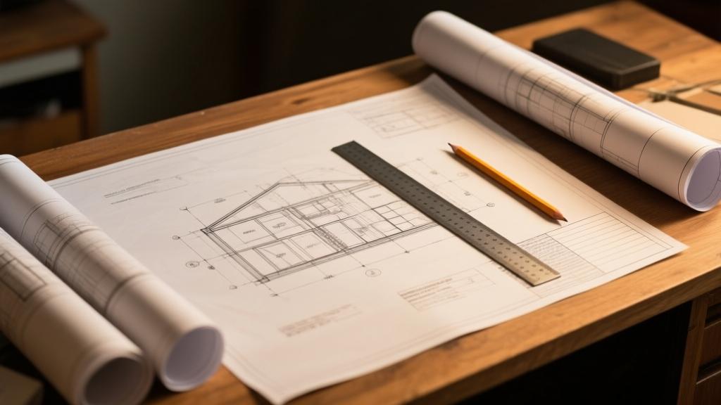
How to Read Construction Drawings and Blueprints for Homeowners - Complete Guide 2026
When you decide to build or renovate a home in India, the most valuable document you will receive from an architect or contractor is the set of construction drawings. These drawings translate the design concept into a language that engineers, masons, electricians and plumbers can all understand. As a homeowner, being able to read and interpret these drawings helps you verify that the work matches your expectations, catch costly mistakes early, and communicate clearly with the construction team.
This guide walks you through every major type of drawing, explains how to read scales and dimensions, decodes common symbols and abbreviations, and offers practical checklists for spotting errors. Whether you are reviewing a simple single-storey plot plan or a detailed multi-storey BIM model, the principles below will empower you to make informed decisions and keep your project on track.
1. Types of Construction Drawings
Construction drawings are organized into several categories, each serving a specific purpose in the building process. The most common categories you will encounter are floor plans, elevations, sections, and detail drawings. Floor plans show the horizontal layout of each level, including walls, doors, windows and major furniture. Elevations illustrate the exterior or interior faces of the building, indicating heights, finishes and openings. Sections cut through the building to reveal interior relationships, such as floor-to-ceiling heights, stair runs and roof structure. Detail drawings zoom in on complex junctions like window heads, stair connections or reinforced concrete joints.
In Indian residential projects, the architect typically provides a set of drawings that includes: site plan, floor plans for each storey, roof plan, elevation drawings for all facades, cross-section drawings, and a series of detail sheets. Each sheet is numbered and referenced in the drawing index, making it easy to locate a specific view. Understanding the purpose of each sheet helps you navigate the drawing set without feeling overwhelmed.
| Drawing Type | Primary Use | Typical Scale (India) |
|---|---|---|
| Site Plan | Shows plot boundaries, setbacks, roads and services | 1:500 or 1:1000 |
| Floor Plan | Layout of walls, doors, windows and furniture | 1:50 or 1:100 |
| Elevation | Exterior or interior facade with heights and finishes | 1:50 or 1:100 |
| Section | Vertical cut showing internal relationships | 1:50 or 1:100 |
| Detail | Zoomed view of specific construction junctions | 1:20 or 1:10 |
For a typical 2 BHK home in Delhi with a built-up area of 1200 sq ft, you might see a floor plan at 1:50 scale, elevations at 1:100, and sections at 1:50. The detail sheets could be at 1:20 to show the reinforcement layout for a beam.
2. How to Read Scales and Dimension Lines
Every drawing includes a scale bar that tells you how a measured length on paper translates to real world dimensions. In India, metric scales dominate, such as 1:50 (1 cm on the drawing equals 50 cm in reality) or 1:100 (1 cm equals 1 m). Some architects also provide a graphic scale bar that you can use with a ruler even if the drawing is printed at a different size.
Dimension lines are the thin lines with arrowheads that indicate the length, width, height or radius of an element. They are usually accompanied by a numeric value and a unit, for example "3500 mm" for a wall length. The dimension line consists of three parts: the extension lines that drop from the object, the dimension line itself, and the text indicating the measurement. Pay attention to whether the dimension is overall (including wall thickness) or net (clear opening).
When reading a drawing, start by checking the scale, then use a ruler or a digital measuring tool to confirm critical dimensions such as room sizes, door widths and stair tread runs. For example, a bedroom marked as 3.6 m x 3.0 m on a 1:50 plan should measure 180 mm by 150 mm on the sheet. If you find a discrepancy, note it immediately for clarification.
- Check the scale bar on each sheet; some sheets may use different scales.
- Verify key dimensions like room lengths, ceiling heights and stair riser heights.
- Use a calibrated ruler or a PDF measuring tool for accuracy.
- Record any mismatches in a notebook for follow-up with the architect.
3. Common Architectural Symbols and Abbreviations
Architectural drawings use a set of standard symbols to represent doors, windows, stairs, furniture, fixtures and more. These symbols are largely universal, but some regional variations exist in India, especially for local building elements like verandas or courtyards. Familiarity with these symbols prevents misinterpretation of the design intent.
Below is a concise table of the most frequently used symbols in Indian residential drawings. The symbols are shown as they appear on a typical plan; the description explains their meaning.
| Symbol | Meaning |
|---|---|
| ○ (circle) | Column (usually reinforced concrete) |
| ---> (double line with arrow) | Door swing direction |
| [ ] (square) | Window opening |
| Staircase zig-zag line | Stair flight (note rise/run) |
| --- (solid line) | Wall (thick line for load-bearing, thin for partition) |
Architects also use abbreviations to save space. Common ones include:
- CLG - Ceiling
- FLR - Floor
- DR - Door
- WIN - Window
- STL - Stair landing
- RCP - Reflected Ceiling Plan
- RCC - Reinforced Cement Concrete
When you see a symbol you do not recognise, refer to the drawing legend usually placed at the bottom or side of the sheet. If the legend is missing, ask the architect for clarification before proceeding.
4. Understanding Structural Drawings
Structural drawings focus on the load-bearing elements of the building: foundations, columns, beams, slabs and reinforcement. These drawings are prepared by a structural engineer and are essential for ensuring the safety and durability of your home. In Indian practice, structural drawings are often identified by the prefix "S-" followed by a sheet number (e.g., S-01, S-02).
A typical column schedule lists each column with its size (e.g., 300 mm x 300 mm), concrete grade (e.g., M25), and reinforcement details (e.g., 4-#12 bars). Beam schedules provide span length, cross-section dimensions, and reinforcement layout (e.g., 2-#16 top, 2-#16 bottom). Reinforcement details are shown with bar sizes in millimetres and spacing, such as "12 mm @ 150 mm" meaning 12-mm diameter bars placed every 150 mm.
Below is a sample column size table for a typical residential building in Mumbai, indicating the approximate load capacity based on common concrete grades.
| Column Size (mm) | Concrete Grade | Typical Load Capacity (kN) |
|---|---|---|
| 250 x 250 | M20 | 200 - 250 |
| 300 x 300 | M25 | 350 - 420 |
| 350 x 350 | M30 | 500 - 600 |
When reviewing structural drawings, use the following checklist to ensure completeness:
- Verify column locations match the architectural floor plan.
- Check beam spans against the specified reinforcement.
- Confirm concrete grades are consistent with the project specifications.
- Look for footings and their dimensions under each column.
- Ensure reinforcement bar sizes are clearly indicated and meet code requirements.
5. Electrical and Plumbing Drawings
Electrical and plumbing drawings are separate sheets that detail the distribution of power, lighting, water supply and drainage throughout the house. Electrical plans typically show the location of switches, sockets, light fixtures, distribution panels and circuit numbers. Plumbing plans illustrate water supply lines, waste pipes, vent stacks and fixture locations such as sinks, toilets and showers.
In Indian residential projects, the electrical drawing may be labelled "E-01" and the plumbing drawing "P-01". Symbols for electrical elements include a circle with a "S" for a switch, a rectangle with a "L" for a light, and a square with a "C" for a circuit breaker. Plumbing symbols include a circle with a "W" for a water tap and a double line with a "D" for a drain pipe.
The following table lists common pipe diameters and their typical uses in Indian homes:
| Pipe Size (mm) | Use | Typical Flow Rate (L/min) |
|---|---|---|
| 15 | Cold water supply to individual fixtures | 10 - 15 |
| 25 | Main water line from meter to house | 30 - 40 |
| 50 | Drainage from bathrooms and kitchen | 80 - 100 |
When you receive the electrical and plumbing drawings, verify the following:
- Switch and socket locations match your functional needs (e.g., TV points in living room).
- Lighting layout provides adequate illumination per Indian standards (minimum 300 lux for living areas).
- Pipe routing avoids structural columns and does not interfere with HVAC ducts.
- Drain slopes are at least 1% to ensure proper flow.
- Compliance with local codes such as the National Building Code of India and state-specific regulations.
6. How to Spot Errors and Inconsistencies
Even well-prepared drawing sets can contain errors, especially when multiple disciplines are coordinated. Common mistakes include mismatched dimensions between architectural and structural plans, missing symbols for fire exits, or conflicts between electrical conduit routes and plumbing pipes. Spotting these issues early can save you from costly rework and schedule delays.
One effective method is to perform a "walk-through" of the drawings using a transparent overlay sheet. Align the floor plan, structural plan and service plan on top of each other and trace key elements like wall lines, column locations and pipe routes. Any misalignment will become evident as a gap or overlap.
Use the following error-spotting checklist for each drawing set:
- Dimension consistency across all sheets (e.g., room length matches on floor plan and structural plan).
- Symbol legend completeness - every symbol used must appear in the legend.
- Service clash detection - ensure electrical conduits do not intersect with water pipes without proper sleeves.
- Code compliance - verify fire escape routes, egress widths and barrier heights.
- Revision dates - ensure you are reviewing the latest version; older revisions may still be circulating.
7. What to Look for When Reviewing Contractor Drawings
Contractors often submit a "shop drawing" or "execution drawing" that translates the design into a buildable format. These drawings may include material tags, construction methods, and sequencing details. As a homeowner, you should verify that the contractor's drawings honor the approved design intent and comply with local regulations.
Key items to review include: material specifications (e.g., brick size, steel grade), finish details (e.g., plaster thickness, tile layout), and any deviations from the original design. If the contractor proposes a change - such as a different column size or an alternative stair design - request a formal variation order with cost implications clearly stated.
Use the following contractor-review checklist to stay organized:
- Material tags match the specification list (e.g., "M25 concrete" for columns).
- Construction sequencing does not conflict with other trades (e.g., electrical work before plastering).
- Dimensional accuracy - verify that door and window openings are sized correctly for the supplied hardware.
- Compliance documents - ensure the contractor has submitted approved structural calculations and fire safety clearances.
- Cost impact - any deviation should be accompanied by a written estimate.
8. Digital Tools for Viewing Blueprints
Modern construction projects increasingly rely on digital formats such as PDF, DWG and BIM (Building Information Modeling). Several tools allow homeowners to view, measure and annotate drawings on a computer, tablet or smartphone. The choice of tool depends on the file format, required features and budget.
Below is a comparison of popular digital tools used in India for viewing construction drawings:
| Tool | File Support | Key Features | Typical Cost (Rs.) |
|---|---|---|---|
| Adobe Acrobat Reader DC | Measure tool, comments, layer visibility | Free (basic) / Rs. 3000 per year (Pro) | |
| AutoCAD Web | DWG, DXF | 2D viewing, basic editing, cloud storage | Rs. 8000 per year |
| SketchUp Viewer | SKP, 3DS | 3D navigation, section cut, measurement | Free (mobile) / Rs. 5000 per year (Pro) |
| Revit BIM 360 Docs | RVT, PDF | Model coordination, clash detection, version control | Rs. 15000 per year (small team) |
For most homeowners, a free PDF viewer with measurement capability is sufficient for reviewing floor plans and elevations. If you are involved in a larger project with multiple stakeholders, consider a cloud-based platform like BIM 360 Docs to keep all revisions in one place and enable real-time comments.
When using digital tools, remember to enable the drawing's scale setting before measuring. Most apps allow you to input the scale (e.g., 1:50) so that on-screen measurements reflect real dimensions. This feature is especially useful when you need to verify clearances for furniture or equipment.
Conclusion
Understanding construction drawings is not reserved for architects or engineers - it is a vital skill for any Indian homeowner who wants to protect their investment. By familiarising yourself with the types of drawings, learning how to read scales, decoding symbols and checking structural, electrical and plumbing details, you can actively participate in the building process and avoid costly surprises.
Use the checklists provided in each section, leverage affordable digital tools, and don't hesitate to ask your architect or contractor for clarification whenever something is unclear. A well-informed homeowner is the best safeguard against errors, delays and budget overruns. Happy building!
Related: Understanding Building Permits for Indian Homeowners